ME 210 Laboratory Experiment: Basic Laboratory
Instruments Purpose: 1. Learn how to measure resistance, voltage, and current with a multi-meter. (You must know how to use a multi-meter in ME 310.) 2. Learn how to measure DC voltage with an oscilloscope. (You must know how to use an oscilloscope in ME 310.) 3. Learn how to properly record data in a laboratory notebook and transfer it to the appropriate sections of the lab report.
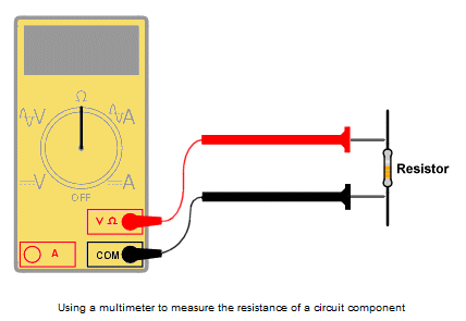
Procedure: Note: This procedure is more detailed than those you will receive in the future. The laboratory assignment will normally state what you should do, but not always give the details of how to do it. This time, you will be given the details of what to write in your laboratory notebook and what to include in your formal laboratory report. In general, the procedure section of your formal laboratory report should include instructions on how to perform any new operations that have not been done in a previous laboratory experiment. 1. Using a pen, mark the first page "page 1" or simply "1" and keep numbering them sequentially as each page is filled. After you fill a page, or quit for the day, sign your name and put the date at the end of your entries. Always use a pen to write in your laboratory notebook. If you make a mistake, simply cross it out, write the correct information, then initial and date the correction. More information about your laboratory notebook can be found at http://courses.byui.edu/ECEN150/RLO/LabNotebookReqs.pdf. 2. Label page 1 in your laboratory notebook as "Basic Laboratory Instruments." This is where you will start recording all the data you will need to write your formal laboratory report about this experiment. More information about your laboratory report can be found at http://courses.byui.edu/ECEN150/RLO/LabReportFormat.pdf. 3. You will need three 1/2 W resistors for this experiment: 220 Ω, 3.3 kΩ, and 47 kΩ. Record the nominal value (color code value) of each resistor in your laboratory notebook. (You will later list this information as calculated or expected data in your formal laboratory report.) Note: Verify the color code. Resistors are sometimes put in the wrong package or storage unit and will not be the value stated on the label. 4. Use a digital multi-meter (DMM) to measure the actual resistance of each resistor.
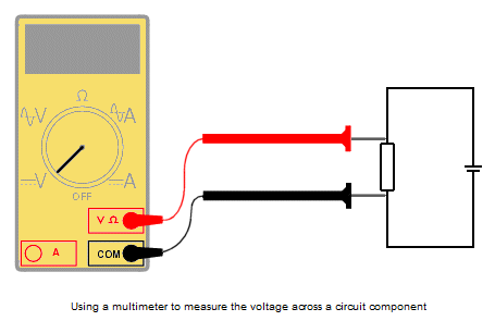
Note: If you forgot how to do this, read the instructions at http://www.ladyada.net/learn/multimeter/resistance.html. (You should provide details about how to do this in the procedure of your formal laboratory report because this is the first experiment where resistance is measured. In the future, you will not be required to explain how to make this measurement. You may want to make some notes in your laboratory notebook to remind you of what to write in your laboratory report.) See an example laboratory report, with the expanded procedure, at http://courses.byui.edu/ECEN150/RLO/ExampleLabReport.pdf. 5. Record the actual resistance of each resistor in your laboratory notebook. (You will later list this information as measured or actual data in your formal laboratory report.) Repeat steps 6 through 16 for each of the three resistors. 6. Connect 5 VDC across the resistor. (You should provide details about how to do this in the procedure of your formal laboratory report because this is the first experiment where the power supply is used.) 7. Draw the schematic diagram for this circuit in your laboratory notebook. (This will go in the schematic diagrams section of you formal laboratory report.) 8. Use a digital multi-meter (DMM) to measure the actual voltage across the resistor.
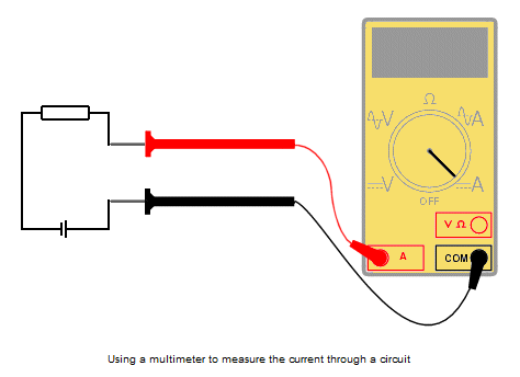
Note: If you forgot how to do this, read the instructions at http://www.ladyada.net/learn/multimeter/voltage.html. (You should provide details about how to do this in the procedure of your formal laboratory report because this is the first experiment where voltage is measured.) 9. Record the actual voltage of each resistor in your laboratory notebook. (You will later list this information as measured or actual data in your formal laboratory report.) 10. Using the nominal resistance (color code value) of the resistor, calculate the expected current through the resistor. (You should provide details about how to calculate this in the procedure of your formal laboratory report.) 11. Record the calculated current through the resistor in your laboratory notebook. (You will later list this information as calculated or expected data in your formal laboratory report.) 12. Use a digital multi-meter (DMM) to measure the actual current through the resistor.
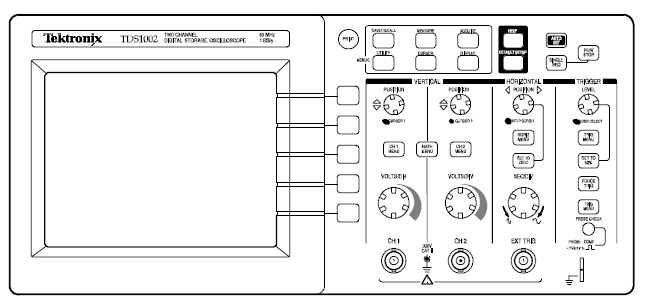
Caution: Never connect test leads across a component when the red lead is plugged into a socket marked "A", "mA", or "ľA", which are often yellow! This will blow the internal fuse. Instead, connect the test leads between the resistor and the power supply, as shown above. Note: If a measurement cannot be obtained, the fuse in your meter may be blown. Ask a Lab Assistant for a new fuse. If a new is not available, determine the measured value of the current by dividing the measured voltage across the resistor by the measured resistance of the resistor. (You should provide details about how to do this in the procedure of your formal laboratory report.) 13. Record the actual current of each resistor in your laboratory notebook. (You will later list this information as measured or actual data in your formal laboratory report.) 14. Using the calculated or expected values of the resistor, calculate its expected power consumption. Is the power rating of the resistor sufficient to handle the actual power consumption? (You should provide details about how to calculate this in the procedure of your formal laboratory report.) 15. Use an oscilloscope to measure the actual DC voltage across the resistor. The oscilloscope is used mostly to measure changing voltages, but it can measure a constant voltage, like 5 VDC, as well. Instructions for the TDS 2000 Series Oscilloscope in the Austin Building:
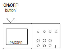
(15a) Power on the oscilloscope. Wait until the display shows that all power-on tests passed.
(15b) Push the DEFAULT SETUP button.
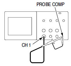
(15c) The default Probe option attenuation setting is 10X. Set the switch to 10X on the oscilloscope probe and connect it to channel 1 on the oscilloscope. To do this, align the slot in the probe connector with the key on the CH 1 BNC, push to connect, and twist to the right to lock the probe in place.
(15d) Connect the probe tip to the 5V PROBE COMP connector and the reference lead (small alligator clip) to the ground PROBE COMP connector. (15d) Push the AUTOSET button.
The Autoset function obtains a stable waveform display for you.
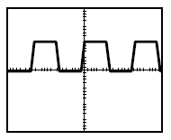
Within a few seconds, you should see a square wave in the display of about 5 V peak-to-peak at 1 kHz.
The oscilloscope is functioning properly and is now ready to make a voltage measurement. (15e) Push the CH 1 MENU button and set the Probe option attenuation to 10X. (15f) Set the switch to 10X on the probe. (15g) Connect the probe tip to the positive side of the resistor and the reference lead (small alligator clip) to the negative side. (15h) Push the AUTOSET button.
The oscilloscope sets the vertical, horizontal, and trigger
controls automatically. (You should provide details about how to do this in the procedure of your formal laboratory report because this is the first experiment where DC voltage is measured with an oscilloscope.) Note: If you more need help doing this, here are some additional resources: The User Manual for the Tektronix TDS 2000 Series oscilloscope, like those in the Austin Building, can be found at http://courses.byui.edu/ECEN150/RLO/LabInstruments/TDSUserManual.pdf. Look at "Taking Simple Measurements" on page 42. A short video clip that demonstrates how to use a digital oscilloscope with an LCD display can be seen at http://courses.byui.edu/ECEN150/RLO/LabInstruments/Oscilloscope.html. Most digital oscilloscopes have similar controls and menus, but the details may be slightly different than those shown. A short video clip that shows the same controls and menus as the TDS 2000 Series digital oscilloscopes on the laboratory benches in the Austin Building can be seen at http://courses.byui.edu/ECEN150/RLO/LabInstruments/TekDigitalScope.html. (No audio.) A short video clip that demonstrates how to use an analog oscilloscope with a CRT display can be seen http://courses.byui.edu/ECEN150/RLO/LabInstruments/TekAnalogScope.html. Most analog oscilloscopes have similar controls, but the layout may be slightly different than those shown. (You should provide details about how to do this in the procedure of your formal laboratory report because this is the first experiment where DC voltage is measured with an oscilloscope.) 16. Sketch the displayed voltage in your in your laboratory notebook. If you are using a digital oscilloscope, you can download the display to your computer for inclusion in your laboratory report. Otherwise, take a digital photograph of the displayed voltage for your laboratory report. (This information will be measured or actual data in your formal laboratory report.) Repeat steps 6 through 16 for each of the other two resistors. 17. Turn off the multi-meter, oscilloscope, and power supply. Put your other equipment and supplies away. Make sure the lab station is clean and ready for the next student. 18. Compare your calculated data to your measured data. Discussion & Conclusions: What conclusions can you make? Start with these: Why are your expected data a little different than your actual data? What are the advantages and disadvantages of the multi-meter and the oscilloscope? How would you choose which one to use for future measurements? Refer to the caution message at step 12; why does the fuse blow when you do this? (Record your conclusions in the discussion & conclusion section of your laboratory report.)
|
