ECEN 150 Laboratory Experiment:
Reactance & Impedance Purpose: 1. Practice calculating reactance and impedance. 2. Observe the phase shift between voltage and current caused by reactance and impedance. 3. Learn how to make AC voltage phase shift measurements with an oscilloscope. 4. Become more familiar with laboratory instruments and reading instrument operating manuals.
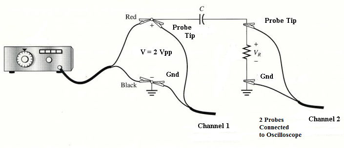
Procedure: Note: The User Manual for the Tektronix TDS 2000 series oscilloscope can be found at http://courses.byui.edu/ECEN150/RLO/LabInstruments/TDSUserManual.pdf. Look at "Functional Check" on page 5 and "Taking Simple Measurements" on page 42. "Cursors" on page 84, "Measure" on page 94, and your Laboratory Report for "Sinusoidal Waveforms" will be especially helpful for this laboratory experiment. The User Manual for the Tektronix CFG 250 Function Generator can be found at http://courses.byui.edu/ECEN150/RLO/LabInstruments/CFGUserManual.pdf. Look at "Operation" in Section 2. 1. Connect a 0.1 μF capacitor and a 1 kΩ resistor to a function generator and an oscilloscope as shown below.
WARNING: It is very important to ALWAYS connect the oscilloscope ground clip to the same node as the function generator ground clip. Both of these ground clips are connected together through the power cords and building wiring. If they are not connected to the same point, a short circuit will result. 2. Calculate and record the reactance (XC) of the 0.1 μF capacitor when connected to a 100 Hz AC voltage. 3. Calculate and record the total impedance (ZT) of the circuit. (ZT = R - j XC = z ∠Ѳ) 4. Calculate and record the period (T) of the 100 Hz AC voltage. 5. Using 2 VPP (with a reference phase angle of 0o) as the total applied voltage (vT) and using the total impedance (ZT) calculated in step # 3, calculate and record the magnitude and phase angle of the current in this circuit. 6. Calculate and record the magnitude and phase angle of the voltage (vR) this current causes to drop across the 1 kΩ resistor. (Remember, i R = i T in series circuits.) 7. Convert the phase angle of this current (i T) from degrees to seconds with the following unit conversion formula: Phase Shift (in seconds) = (T / 360o) * (phase angle of i T) (The degrees cancel out and the result is in seconds.) 8. Record the calculated phase shift (in seconds). 9. Use the oscilloscope measurements on channel 1 to adjust the function generator for a 100 Hz sine wave output voltage (vT) of 2 VPP. Refer to the User Manuals for details of how to do this.
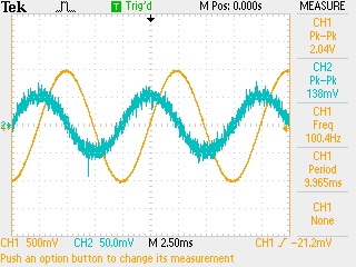
10. Display the voltage across the resistor on channel 2 of the oscilloscope and superimpose it on the total voltage shown on channel 1. Increase the display size of the much smaller voltage on channel 2 by adjusting the VOLTS/DIV knob. This may result in a fat, fuzzy waveform, which is normal when amplifying a small signal.
11. You should be able to see the phase angle (phase shift) between the two voltages. Stretch out the horizontal size of the waveforms with the SEC/DIV knob to make measuring the phase angle easier.
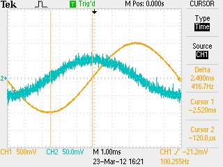
12. Set the left cursor over the voltage on channel 2 where it crosses the horizontal graticule, as show above. Refer to the User Manuals for details of how to do this. 13. Place the right cursor over the voltage on channel 1 where it crosses the horizontal graticule, as show above. 14. Determine and record the measured number of seconds (Δt) between the two cursors. 15. Use the Tektronix "OpenChoice Desktop" software to record an image of the display or take a digital photo of the display for your lab report. 16. Convert the time (Δt) recorded in step # 14 to degrees with the following unit conversion formula: Phase Angle (in degrees) = (Δt / T) * (360o) (The seconds cancel out and the result is in degrees.) 17. Record the measured phase shift (in degrees) between the displayed voltages, which is the actual phase shift of the current (i T).
Discussion & Conclusions: What conclusions can you make? Start with these: Why is the voltage across the resistor so much smaller than the applied voltage? Why is it necessary to include a phase angle with the magnitude of voltage, current, and impedance in AC circuits? How are the phase angles of the voltage, current, and impedance related? We determined the actual phase shift of the current in this circuit by measuring the phase shift of the voltage across the resistor; why is the voltage across the resistor in phase with the total current, but out of phase with the total applied voltage?
|